IntelligentGraph embeds calculation and analysis capability within RDF knowledge graphs, rather than forcing analysis to be undertaken by exporting query results to external analysis applications such as Excel.

IntelligentGraph achieves this by embedding scripts into the RDF knowledge graph which are evaluated when queried with SPARQL.

Scripts, written in a variety of languages such as JavaScript, Java, and Python, access the underlying graph using simple pathPatternQL navigation.

IntelligentGraph=KnowledgeGraph+Embedded Analysis.pdf

Why IntelligentGraph?

At present calculations over stored data are either delivered by custom code or exporting the stored data to spreadsheets. The data behind these tools is inevitably tabular. In fact, so dominant are spreadsheets for analysis that the spreadsheet itself becomes the ‘database’ with the inherent difficulties of syncing that data with the source system of record.

The real-world is better represented as a network or graph of interconnected things Therefore a knowledge graph is a far better storage organization than tables or objects. However, there is still the need to perform ad hoc numerical analysis over this data. 

RDF DataCube can help organize data for analysis, but still the analysis has to be performed externally. Confronted with this dilemma, knowledge graph data would typically be exported in tabular form to a datamart or directly into, yet again, a spreadsheet where the analysis could be performed.

IntelligentGraph turns this approach on its head by embedding the calculations as scripts within the knowledge graph. These scripts are evaluated on query, and utilise the data in situ: no concurrency issues.. This allows the calculations to have knowledge of its neighbouring nodes and edges, just like Excel cells can access other cells in the spreadsheet. Access to other nodes within the graph uses pathPatternQL navigation.

Example Data and Analysis

An Industrial Internet of Things (IIoT) application is connecting all the measurements about a process plant, such as an oil refinery, into a knowledge graph that relates the measurements to the material flows through the process equipment.

Although there is an abundance of measurements and laboratory analyses available, the values required for operating and performance monitoring are not (and mostly cannot) be directly measured. 

For example:

  • Stream Mass-Flow: direct mass flow measurements are rare. Instead, a volume flow measurement is used in conjunction with a measured material density to calculate the mass-flow
  • Unit Mass Flow Throughput: this is calculated by summing either all feed stream mass flows or product stream mass flows.
  • Unit Mass Balance: this is calculated by differencing the feed from product mass flows
  • Product Stream Yield: this is the ratio of a stream’s mass-flow to the unit to which the stream is connected throughput.

Figure 1: Typical Process Flow Sheet

These are simple examples; however, they show the reliance on the knowledge graph structure to perform the analysis.

Solving data analysis, the traditional way

Data is in the database, analysis is done by the analysis engine (aka Excel), right?

Figure 2: Data analysis the traditional way

In this scenario, the local power user sets up a query to export data from the database and converts to a format that can be imported into Excel. Ever increasingly complex formulae are then written to wrangle the data into the results that are required.

Why is the spreadsheet approach risky?

  • The analysis is now separated from the data. Data changes will not be reflected in the analysis. Worse still, changes to the analysis might not be propagated to all the spawned copies of the spreadsheet.
  • The data is separated from the analysis. The analysis results are rarely re-imported into the data store where data vs analysis could be performed. Instead, even more data is extracted into the spreadsheet.
  • The difficultly of managing the separation of data from analysis becomes so great that in many cases the database is dispensed with entirely and the spreadsheet becomes the de-facto database.

Solving data analysis with an IntelligentGraph

The beauty of Excel is that a cell can contain either a value or a formula that can reference other cell’s values. Why not do the same with a graph: a node can have edges that terminate with a literal value, or a formula that can reference other node’s values.

This is illustrated in the diagram below:

  • The :massFlow property is not measured directly, so a formula is used for its value instead. This formula references $this, the node to which the calculation is attached, and uses the method getFact() to retrieve related values. The argument of getFact() is a pathPatternQL expression.
  • The :totalProduction property is not measured directly, so a formula is used instead which iterates over all of the ‘stream out’ nodes, retrieving the value of the :massFlow for each stream. The :massFlow value is, of course, in turn a calculation.

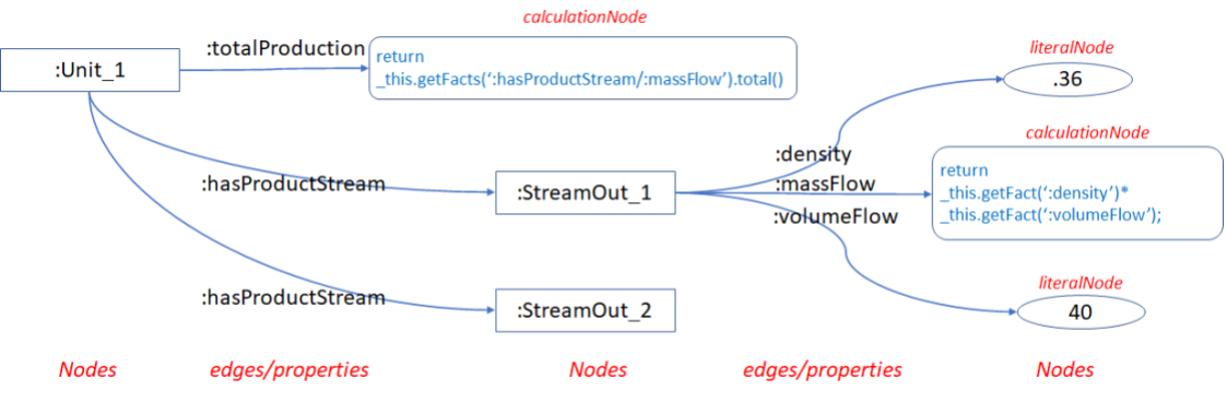
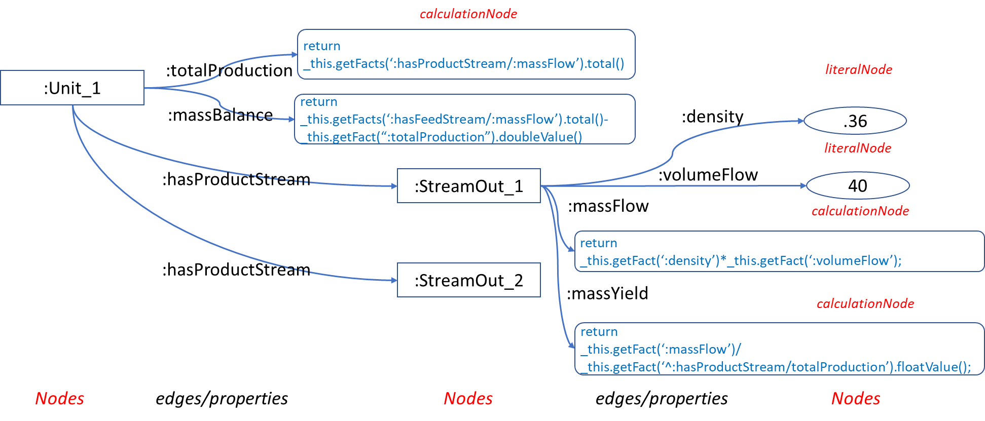
Figure 3: Intelligent Graph Data Analysis

Why is the IntelligentGraph approach so advantageous?

  • There is no separation between data and analysis, removing the risk of stale and inaccurate data and calculations.
  • The calculations embedded within the graph can take advantage of the knowledge that is contained within that graph. This makes the calculations far simpler than those that need to be embedded in spreadsheets.
  • The calculations will automatically utilize on the fly the changing knowledge.

How does IntelligentGraph Work?

Analysis is embedded in an IntelligentGraph simply by adding script literals as object values of subjects with datatype of the scripting language (groovy, javascript, python etc).

The IntelligentGraph engine is provided as an RDF4J Stackable SAIL. This means that its capabilities can be combined with any other RDF4J capabilities. The choice of RDF storage remains the same as for any other RDF4J compliant framework.

Modeling with Scripts

Typically, a graph node will have associated attributes with values, such as a stream with volumeFlow and density values:

Stream Attributes:

:Stream_1
   :density ".36"^^xsd:float ;
   :volumeFlow "40"^^xsd:float .

Of course, in the ‘real-world’ these measured values are sourced from outside the KnowledgeGraph and change over time. IntelligentGraph can deal with both of these requirements.

The ‘model’ of the streams can be captured as edges associated with the Unit:

:Unit_1
   :hasProductStream :Stream_1 ;
   :hasProductStream :Stream_2 ;
.

Calculate Mass Flow

The calculations are declared as literals[1] with a datatype whose local name corresponds to one of the installed script languages:

:Stream_1 :massFlow     
    "_this.getFact(':density')*    
     _this.getFact(':volumeFlow');"^^:groovy .

Calculate Total Production

A typical performance metric is to understand the total production from a unit, which is not of course directly measured. However, it can be easily expressed using existing calculated values:

:Unit_1   :totalProduction
    "var totalProduction =0.0;
    for(Resource stream : _this.getFacts(':hasProductStream'))
    {
        totalProduction += stream.getFact(':massFlow');
    }
    return totalProduction; "^^:groovy .

Instead of returning the object literal value (aka the script), the IntelligentGraph will return the result value for the script.

We can write this script even more succinctly using the expressive power PathQL:

:Unit_1  :totalProduction  
    "return _this.getFacts(':hasProductStream/:massFlow').total(); "^^:groovy

However, IntelligentGraph allows us to build upon existing calculations to simply express what would normally be difficult-to-calculate metrics, such as product yield or mass balance.

Calculate Mass Yield

Any production unit has different valued products. So a key metric is the yield of individual streams. This can easily be calculated as follows, using values that are themselves calculations.

var result= _this.getFact(":massFlow").floatValue()/ 
_this.getFact("^:hasStream/:totalProduction").floatValue();  
result;

Calculate Mass Balance

Measurements are not perfect, nor is the operation of a unit. One of the first indicators of a problem is when the mass flow in does not match the mass flow out. This can be expressed as another calculated property of a Unit:

return  _this.getFacts(":hasFeedStream/massFlow").total() -_this.getFacts(":totalProduction").total();

Querying Results

Access to the calculated values is via standard-SPARQL. However instead of returning the script literal, IntelligentGraph will invoke the script engine, 

Thus to access the :massFlow calculated value, the SPARQL is simply:

select ?massFlow
{
 :Stream_1 :massFlow ?massFlow 
}

If the script literal is required then the object variable can be postfixed with _SCRIPT:

select ?massFlow ?massFlow_SCRIPT 
{
 :Stream_1 :massFlow ?massFlow, ?massFlow_SCRIPT 
}

If a full trace of the calculation, including tracing calls to other scripts, is required then the object variable can be postfixed with _TRACE:

select ?massFlow ?massFlow_TRACE 
{
 :Stream_1 :massFlow ?massFlow, ?massFlow_TRACE 
}

How to Write IntelligentGraph Scripts?

Script Languages

Any Java 9 supported language can be used simply by making the corresponding language JAR available. 

By default, JavaScript, Groovy, Python JAR are installed. The complete list of compliant languages is as follows

AWK, BeanShell, ejs, FreeMarker, Groovy, Jaskell, Java, JavaScript, JavaScript (Web Browser), Jelly, JEP, Jexl, jst, JudoScript, JUEL, OGNL, Pnuts, Python, Ruby, Scheme, Sleep, Tcl, Velocity, XPath, XSLT, JavaFX Script, ABCL, AppleScript, Bex script, OCaml Scripting Project, PHP, Python, Smalltalk, CajuScript, MathEclipse

Script Context Variables

In addition, each script has access to the following predefined variables that allow the script to access the context within which it is being run.

  • _this, a Thing corresponding to the subject of the triples for which the script is the object.  Since this available, helper functions are provided to navigate edges to or from this ‘thing’ below:
  • _property, a Thing corresponding to the predicate or property of the triples for which the script is the object.
  • _customQueryOptions, a HashMap<String, Value> of name/value pairs corresponding to the pairs of additional arguments to the SPARQL extension function. These are useful for passing application-specific parameters.
  • _builder, a RDF4J graph builder object allowing a graph to be constructed (and manipulated) within the script. A graph cannot be returned from a SPARQL function. However the IRI of the graph can be returned, and any graph created by a script will be persisted.
  • _tripleSource, the RDF4J TripleSource to which the subject, predicate, triple belongs.

Fact and Path Functions

The spreadsheets’ secret sauce is the ability of a cell formula to access values of other cells, either individually or as a set. The IntelligentGraph provides this functionality with several methods associated with Thing, which are applicable to the _this Thing initiated for each script with the subject Thing.

Thing.getFact(String pathPattern) returns Value

Returns the value of node referenced by the pathPattern, for example “:volumeFlow” returns the object value of the :volumeFlow edge relative to _this node. The pathPattern allows for more complex path navigation.

Thing.getFacts(String pathPattern) returns Values

Returns the values of nodes referenced by the pathPattern, for example “:hasProductStream” returns an iterator for all object values of the :hasProductStream edge relative to _this node. The pathPattern allows for more complex path navigation.

Thing.getPath(String pathQL) returns Path

Returns the first (shortest)  path referenced by the pathQL, for example “:parent{1..5}” returns the path to the first ancestor of _this node. The pathQL allows for more complex path navigation.

Thing.getPaths(String pathQL) returns PathResults

Returns all paths referenced by the pathQL, for example :parent{1..5}” returns an iterator, starting with the shortest path,  for all paths to the ancestors of _this node. The pathQL allows for more complex path navigation.

Path Patterns

Spreadsheets are not limited to accessing just adjacent cells; neither is the IntelligentGraph. PathPatterns provide a powerful way of navigating from one Thing node to another. PathPatterns are inspired by SPARQL and propertyPaths, but a richer, more expressive, PathQL was required for the IntelligentGraph.

Examples

Examples of PathQL patterns are as follows:

_this.getFact(“:hasParent”)

will return the first parent of $this.

_this.getFact(“^:hasParent”)

will return the first child of $this.

_this.getFacts(“:hasParent/:hasParent”)

will return the grandparents of $this.

_this.getFacts(“:hasParent/^:hasParent”)

will return the siblings of $this.

_this.getFacts(“:hasParent[:gender :female]/:hasParent”)

will return the maternal grandparents of $this

_this.getFacts(“:hasParent[:gender :female]/:hasParent[:gender :male]”)

will return the maternal grandfather of $this.

_this.getFacts(“:hasParent[:gender [ rdfs:label “female”]]”)

will return the mother of $this but using the label instead of the IRI.

_this.getFacts(“:hasParent[eq :Peter]/:hasParent[:gender :male]”)

will return the grandfather of $this, who is the parent of :Peter.

_this.getFacts(“:hasParent[ne :Peter]/:hasParent[:gender :male]”)

will return grandfathers of $this, who are not the parent of :Peter.

The following diagram visualizes a path through a genealogical graph, from _this to the find the parents of a maternal grandfather born in Maidstone:

_this.getFacts(“/:parent[:gender :female]/:parent[:gender :male, :birthplace [rdfs:label ‘Maidstone’]]/:parent”)


Figure 4: PathPatternQL Example

How Is Performance?

IntelligentGraph takes the following actions to improve performance:

  1. All intermediate calculation results are cached, keyed by the subjectNode, predicate, and customQueryOptions.
  2. Cache can be cleared using the SPARQL function ClearCache.
  3. The SPARQL function ObjectValue takes as its argument the subject, predicate and objectValue. If the objectValue supplied is not of script datatype, the function will immediately return the objectValue.
  4. Circular functions, in which A calls B calls A, are detected and rejected.

Can I Debug?

Since IntelligentGraph combines calculations with the knowledge graph, it is inevitable that any evaluation will involve calls to values of other nodes which are in turn calculations. For this reason,  IntelligenrtGraph supports tracing and debugging:


Figure 4: Tracing Calculation

How Do I Add Intelligence to my RDFGraph?

Download

The project is located in Github, from where the intelligentgraph.jar can be downloaded from there:

The intelligentgraph.jar does not include all of the scripting etc language dependencies, so to use it you would have to be certain all dependencies are already available.

Install

IntelligentGraphwill work only with RDF4J version 3.3.0 and above. 

Copy intelligentgraph.jar

To  /usr/local/tomcat/webapps/rdf4j-server/WEB-INF/lib/intelligentgraph.jar

The RDF4J server will need to be restarted for it to recognize this new JAR and initiate the scripting engine.

[1] In this case the script uses Groovy, but any Java 9 compliant scripting language can be used, such as JavaScript, Python, Ruby, and many more.

Providing answers to users’ analysis, searching, visualizing or other questions of their own data

Creating an overall solution that presents data in a useful way can be challenging, but OData2SPARQL and Lens2OData solves this.

  • RDF-Graph: Data + Model = Information, allowing us to combine you raw data with an adaptable model to create meaningful information
  • OData2SPARQL: Information + Rules = Knowledge, provides you the ability to access that information combine with additional rules (SPIN and SHACL) to deliver useful knowledge that can be consumed by applications and BI tools.
  • Lens2OData: Knowledge + Action = Results, allows users to easily navigate, search, explore, and visualize this knowledge in such a way that it is easy to take action and produce results.

To see this all in action we have prepared a demonstrator that can be downloaded, and the following videos which illustrate the capabilities of this demonstrator.

  • Explore provenance of data sources which is retained by RDF- graph and OData2SPARQL rather than losing that provenance with typical ETL processing.

  • Explore the Transport For London train lines, stations and zones, illustrating how easy it is to transform any dataset to RDF_Graph and immediately get the benefits of OData access, and Lens UI/UX

To download and run this demonstrator go toDocker hub here

SQL2RDFincremental materialization uses a stream of source data changes (DML) and transforms them to the corresponding changes (inserts, deletes) in the triple store ensuring concurrency between RDBMS and triplestore. SQL2RDFincremental materialization is based on the same R2RML mapping used for virtualization (Ontop), and (Capsenta), and materialization (In4mium, and R2RML Parser) thus does not incur an additional configuration maintenance problem.

Mapping an existing RDBMS to RDF has become an increasingly popular way of accessing data when the system-of-record is not, or cannot be, in a RDF database. Despite its attractiveness, virtualization is not always possible for various reasons such as performance, the need for full SPARQL 1.1 support, the need to reason over the virtualized as well as other materialized data, etc. However materialization of an existing RDBMS to RDF is also not an ideal alternative. Reasons include the inevitable lack of concurrency between the system-of-record and the RDF.

Thus incremental materialization provides an alternative between virtualization and materialization, offering:

  • Easy ETL of source RDB as no additional configuration required other than the same R2RML required for virtualization or bulk materialization.
  • Improved concurrency of data compared with materialization.
  • Significantly less computational overhead than a full materialization of the source data.
  • Improved query performance compared with virtualization especially when reasoning is required.
  • Compatibility with R2RML thus reducing configuration maintenance.
  • Supports insert, update, and delete changes on the source RDBMS.
  • Source transactions can be batched, and the changes to the triplestore are part of a single transaction that can be rolled back in the event of a problem.
  • Supports change logging so that committed changes can be rolled back.

Contact  inova8 if you would like to try SQL2RDF

When a subject-matter-expert (SME) describes their data domain they use English language. In response we give them visually beautiful, but often undecipherable, diagrams. Here we propose an alternative: a ‘word-model’ that describes the model in structured English without loss of accuracy or completeness.

Creating an ontological model invariably involves a subject-matter-expert (SME) who has an in-depth knowledge of the domain to be modelled working together with a data modeler or ontologist who will translate the domain into an ontological model.

When a subject-matter-expert (SME) is in discussion with a data modeler, they will be describing their information using English language:

“I have customers who are assigned to regions, and they create orders with a salesperson who prepares the order-details and assigns a shipper that operates in that region”

In response a data modeler will offer the subject-matter-expert (SME) an E-R diagram or an ontology graph!

Figure 1: Geek Model Diagrams

No wonder we are regarded as geeks! Although visually appealing, they are difficult for an untrained user to verify the model that the diagram is describing.

Instead we could document the model in a more easily consumed way with a ‘word-model’. This captures the same details of the model that are present in the various diagrams, but uses structured English and careful formatting as shown below.

aCustomer

  • places anOrder
    • made by anEmployee
      • who reports to anotherEmployee
      • and who operates in aTerritory
    • and contains anOrderDetail
      • refers to aProduct
        • which is supplied by aSupplier
        • and which categorized as aCategory
      • and is shipped by aShipper
      • and is assigned to aRegion
        • which has aTerritory
      • and belongs to aRegion

The basic principle is that we start at any entity, in this case ‘Customer’ and traverse the edges of the graph that describe that entity. At each new node we indent. Each line is a combination of the predicate and range class. No rules regarding order in which we visit the nodes and edges. No rules regarding depth. The only rule should be that, if we want a complete word-model, the description traverses all edges in one direction or the other.

These word-models are useful in the model design phase, as they are easy to document using any editor. Since the word-model is in ‘plain English’, it is easy for a SME to verify the accuracy of the model, and mark up with comments and edits. However word-models are also easy to generate from an RDF/OWL model.

Enhancements to Word-Model

We can refine the contents of the word-model as we develop the model with the SME. We can also enhance the readability by decorating the word-model text with the following fonts:

Word-Model Legend
Italics indicate an instance of a class, a thing
Bold indicates a class
Underline is a predicate or property that relates instances of classes
BoldItalic is used for cardinality expressions

Level 1a: Add the categorization of entities

Rather than using an example of an entity, we can qualify with the class to which the sample entity belongs.

aCustomer, a Customer

  • places anOrder, an Order
    • made by anEmployee, an Employee
      • who reports to anotherEmployee, an Employee
      • and who operates in aTerritory, a Territory
    • and contains anOrderDetail, an OrderDetail
      • and refers to aProduct, a Product
        • which is supplied by aSupplier, a Supplier
        • and which is categorized as aCategory, a Category
      • and is shipped by aShipper, a Shipper
      • and is assigned to aRegion, a Region
        • which has aTerritory, a Territory
      • and belongs to aRegion, a Region

Level 1b: Add cardinality of predicates

We can also add the cardinality as a modifier between the predicate and the entity:

aCustomer

  • who places zero, one or more orders
    • each made by one anEmployee
      • who reports to zero or one anotherEmployee
      • and who operates in one or more aTerritorys
    • and each contains one or more anOrderDetails
      • which refers to one aProduct
        • which is supplied by one aSupplier
        • and which is categorized as one aCategory
      • and is shipped by one aShipper
      • and is assigned to one aRegion
        • which has one or more aTerritorys
      • and belongs to one aRegion

Level 2: Add categorization and cardinality

Of course we can combine these extensions into a single word-modol as shown below.

aCustomer, a Customer

  • who places zero, one or more orders, each an Order
    • each made by one anEmployee, an Employee
      • who reports to zero or one anotherEmployee, an Employee
      • and who operates in one or more aTerritorys, each a Territory
    • and each contains one or more anOrderDetails, each an OrderDetail
      • which refers to one aProduct, a Product
        • which is supplied by one aSupplier, a Supplier
        • and which is categorized as one aCategory, a Category
      • and is shipped by one aShipper, a Shipper
      • and is assigned to one aRegion, a Region
        • which has one or more aTerritorys, each a Territory
      • and belongs to one aRegion, a Region

Despite the completeness of what is being described by this word-model, it is still easy to read by SMEs.

Auto-generation of Word-Model

Once the word-model has been formally documented in RDF/OWL, we can still use a word-model to document the RDF/OWL by auto-generating a word-model from the underlying RDF/OWL ontology as shown below.

Figure 2: Word-Model

This was generated using a SPIN magic-property as follows:

select ?modelDefinition
{
   (model:Customer 4 false) :modelDefinition ?modelDefinition .
}

This auto-generation can go further by including the datatype properties associated with each entity as shown below:

Figure 3: Word-Model including datatype properties

This was generated using a SPIN magic-property as follows:

select ?modelDefinition
{
   (model:Customer 4 true) :modelDefinition ?modelDefinition .
}

Appendix

SPIN Magic Properties:

The following SPIN properties were defined for auto generation of the word-model in HTML format:

classProperties

SELECT ?classProperties
WHERE {
{SELECT  ?arg1   (    IF(?arg2CONCAT("(",?properties,")"),"") as ?classProperties) WHERE
    {
        SELECT ?arg1 ((GROUP_CONCAT(CONCAT("<i>", ?dataPropertyLabel, "</i>"); SEPARATOR=', ')) AS ?properties)
        WHERE {
           # BIND (model:Product AS ?arg1) .
            ?arg1 a ?class .
            FILTER (?class IN (rdfs:Class, owl:Class)) .
            ?arg1 rdfs:label ?classLabel .
            ?dataProperty a owl:DatatypeProperty .
            ?dataProperty rdfs:domain ?arg1 .
            ?dataProperty rdfs:label ?dataPropertyLabel .
        }
        GROUP BY ?arg1
    }
}
}

classDefinition

SELECT ?classDefinition ?priorPath
WHERE {
    {
        SELECT ?arg1 ?arg2  ((GROUP_CONCAT( ?definition; SEPARATOR='<br/>and that ')) AS ?classDefinition)  ((GROUP_CONCAT( ?pastPath; SEPARATOR='\t')) AS ?priorPath)
        WHERE {
           ?arg1 a ?class . FILTER( ?class in (rdfs:Class, owl:Class ))
            ?arg1 rdfs:label ?classLabel .
            ?objectProperty a owl:ObjectProperty .
            {
                        ?objectProperty rdfs:domain ?arg1 .
                        ?objectProperty rdfs:label ?objectPropertyLabel .
                        ?objectProperty rdfs:range ?nextClass .
                        ?nextClass rdfs:label ?nextClassLabel .   BIND(?objectProperty as ?property)
            }UNION{
                        ?objectProperty  owl:inverseOf ?inverseObjectProperty .
                        ?objectProperty rdfs:domain  ?nextClass.
                        ?inverseObjectProperty rdfs:label ?objectPropertyLabel .
                        ?objectProperty rdfs:range ?arg1 .
                        ?nextClass rdfs:label ?nextClassLabel .    BIND(?inverseObjectProperty as ?property)
            }UNION{
                        ?inverseObjectProperty  owl:inverseOf ?objectProperty .
                        ?objectProperty rdfs:domain  ?nextClass.
                        ?inverseObjectProperty rdfs:label ?objectPropertyLabel .
                        ?objectProperty rdfs:range  ?arg1 .
                        ?nextClass rdfs:label ?nextClassLabel .    BIND(?inverseObjectProperty as ?property)
            }
#Stop from going too deep
            BIND(?arg2 -1 as ?span) FILTER(?span>0). 
            ?nextClass a ?nextClassClass. FILTER( ?nextClassClass in (rdfs:Class, owl:Class ))
#,  odata4sparql:Operation))  .
#Do not process an already processed arc (objectProperty)         
            BIND(CONCAT(?arg4,"\t",?objectPropertyLabel) as ?forwardPath) FILTER( !CONTAINS(?arg4, ?objectPropertyLabel ))  
            (?nextClass ?span ?arg3 ?forwardPath ) :classDefinition (?nextClassDefinition  ?nextPath).           
#Do not include if arc (objectProperty) appears already   
            FILTER(  !CONTAINS(?nextPath, ?objectPropertyLabel )) BIND(CONCAT( ?objectPropertyLabel, IF(?nextPath="","",CONCAT("\t",?nextPath))) as ?pastPath)
                                    (?nextClass ?arg3) :classProperties ?nextClassProperties .
            BIND (CONCAT("<u>",?objectPropertyLabel , "</u> <b>", ?nextClassLabel, "</b>",  ?nextClassProperties, IF ((?nextClassDefinition!=""), CONCAT("<br/><blockquote>that ",  ?nextClassDefinition, "</blockquote>"), "")  ) as ?definition)
        }
        GROUP BY ?arg1 ?arg2
    } .
}

modelDefintion

SELECT ?modelDefinition
WHERE {
    {
        SELECT ?arg1 ?arg2 ?arg3 ((CONCAT("<b>", ?classLabel, "</b>", ?nextClassProperties, "<blockquote>that ", ?classDefinition, "</blockquote>")) AS ?modelDefinition)
        WHERE {
           # BIND (model:Order AS ?arg1) .  BIND (4 AS ?arg2) . BIND (false AS ?arg3) .
            ( ?arg1 ?arg2 ?arg3 "") :classDefinition (?classDefinition "") .
            ( ?arg1 ?arg3 ) :classProperties ?nextClassProperties .
            ?arg1 rdfs:label ?classLabel .
        }
    } .
}

Usage

The following will return the HTML description of the model, starting with model:Customer, stopping at a depth of 4 in any direction, and not including the datatypeproperty definition.

select ?modelDefinition
{
   (model:Customer 4 false) :modelDefinition ?modelDefinition .
}

Let’s face it, RDF Graph datastores have not become the go-to database for application development like MySQL, MongoDB, and others have. Why? It is not that they cannot scale to handle the volume and velocity of data, nor the variety of structured and unstructured types.

Perhaps it is the lack of application development frameworks integrated with RDF. After all any application needs to not only store and query the data but provide users with the means to interact with that data, whether it be data entry forms, charts, graphs, visualizations and more.

However application development frameworks target popular back-ends accessible via JDBC and, now we are in the 21century, OData. RDF and SPARQL are not on their radar … that is unless we wrap RDF with OData so that the world of these application development environments is opened up to RDF Graph datastores.

OData2SPARQL provides that Janus-inflexion point, hiding the nuances of the RDF Graph behind an OData service which can then be consumed by powerful development environments such as OpenUI5 and WebIDE.

This article shows how an RDF Graph CRUD application can be rapidly developed, yet without losing the flexibility that HTML5/JavaScript offers, from which it can be concluded that there is no reason preventing the use of RDF Graphs as the backend for production-capable applications.

A video of this demo can be found here: https://youtu.be/QFhcsS8Bx-U

Figure 1: OData2SPARQL: the Janus-Point between RDF data stores and application development

Rapid Application Development Environments

There are a great number of superb application development frameworks that allow one to create cross platform (desktop, web, iOS, and Android), rich (large selection of components such as grids, charts, forms etc) applications. Most of these are based on the MVC or MVVM model both of which require a systematic and complete (CRUD) access to the back-end data via a RESTful API. Now that OData has been adopted by OASIS, the number of companies offering explicit support for OData is increasing, ranging from Microsoft, IBM, and SAP. Similarly there are a number of frameworks, one of which is SAPUI5 which has an open source version OpenUI5.

OpenUI5

OpenUI5 is an open source JavaScript UI library, maintained by SAP and available under the Apache 2.0 license. OpenUI5 lets you build enterprise-ready web applications, responsive to all devices, running on almost any browser of your choice. It’s based on JavaScript, using JQuery as its foundation, and follows web standards. It eases your development with a client-side HTML5 rendering library including a rich set of controls, and supports data binding to different models (JSON, XML and OData).

With its extensive support for OData, combining OpenUI5 with OData2SPARQL releases the potential of RDF Graph datasources for web application development.

Web IDE

SAP Web IDE is a powerful, extensible, web-based integrated development tool that simplifies end-to-end application development. Since it is built around using OData datasources as its provider, then WebIDE can be used as a semantic application IDE when the RDF Graph data is published via OData2SPARQL.

WebIDE runs either as a cloud based service supplied free by SAP, or can be downloaded as an Eclipse ORION application. Since the development is probably against a local OData endpoint, then the latter is more convenient.

RDF Graph application in 5 steps:

  1. Deploy OData2SPARQL endpoint for chosen RDF Graph store

The Odata2SPARQL war is available here, together with instructions for configuring the endpoints: odata2sparql.v2

The endpoint is this example is against an RDF-ized version of the ubiquitous Northwind databases. This RDF graph version can be downloaded here: Northwind

  1. Install WebIDE

Instructions for installing the Web IDE Personal edition can be found here: SAP Web IDE Personal Edition

  1. Add OData service definition

Once installed an OData service definition file (for example NorthwindRDF) can be added to the SAPWebIDE\config_master\service.destinations\destinations folder, as follows

Description=Northwind

Type=HTTP

TrustAll=true

Authentication=NoAuthentication

Name=NorthwindRDF

ProxyType=Internet

URL=http://localhost:8080

WebIDEUsage=odata_gen

WebIDESystem=NorthwindRDF

WebIDEEnabled=true

  1. Create new application from template

An application can be built using a template which is accessed via File/New/Project from Template. In this example the “CRUD Master-Detail Application” was selected.

The template wizard needs a Data Connection: choose Service URL, select the data service (NorthwindRDF) and enter the path of the particular endpoint (/odata2sparql/2.0/NW/).

Figure 2: WEB IDE Data Connection definition

At this stage the template wizard allows you to browse the endpoint’s entityTypes and properties, or classes and properties in RDF graph-speak.

Since the Web IDE and OpenUI5 is truly model driven, the IDE creates a master-detail given the entities that you define in the next screen.

The template wizard will ask you for the ‘object’ entityType which in this example is Category. Additionally you should enter the ‘line item’ but in this case there is only one navigation property (aka objectproperty in RDF graph-speak) which is the products that belong to the category.

Note that this template allows other fields to be defined, so titls and productUnitprice were selected.

Figure 3: WEB IDE Template Customization

  1. Run the application

The application is now complete and can be launched from the IDE. Right-click the application and select Run/Run as/As web application:

Figure 4: Application

Even this templated application is not limited to browsing data: it allows full editing of the categories. Note that even the labels are derived from the OData endpoint, but of course they can be changed by editing the application.

Figure 5: Edit Category

Alternatively a new category can be added:

Figure 6: Create New Category

Next Steps

That’s it: a fully functional RDF Graph web application built without a single line of code being written. However we can chose to use this just as a starting point:

  1. Publish data views, the SPARQL equivalent of a SQL view on the data, to the OData2SPARQL endpoint.
    • These are particularly useful when publishing reports in OpenUI5, Excel PowerQuery, Spotfire, etc.
  2. Modify the model that is published via the OData2SPARQL endpoint
    • The model that is published is extracted from the schema defined in the endpoint configuration. Thus the schema can be changed to suit what one wants in the endpoint metamodel.
  3. Edit the templated application
    • The templated application is just a starting point for adaptation: the code that is created is nothing more than standard HTML5/JavaScript using the OpenUI5 libraries.
  4. Build the application from first-principles
    • A template is not always the best starting point, so an application can always be built from first-principles. However the OpenUI5 libraries make this much easier by, for example, making the complete metamodel of the OData2SPARQL endpoint available within the application simply by defining that endpoint as the datasource.

Integration Problem to be solved

  • Data in different databases, even with Linked Open data sources.
  • Misaligned models, different datasets have different meanings for classes and predicates that need to be aligned.
  • Misaligned names for the same concepts.
  • Replication is problematical.
  • Query definition and scope of querying difficult to define in advance.
  • Provence of data necessary.
  • Cannot depend on inferences being available in advance
  • Scalable architecture requires that all queries are stateless

Data Cathedrals versus Information Shopping Bazaars

Linked Open Data has been growing since 2007 from a few (12) interconnected datasets to 295 as of 2011, and it continues to grow. To quote “Linked Data is about using the Web to connect related data that wasn’t previously linked, or using the Web to lower the barriers to linking data currently linked using other methods.” (Linked Data, n.d.) 

Figure 1: Growth of the Linked Data ‘Cloud’

As impressive as the growth of interconnected datasets is, what is more important is the value of that interconnected data. A corollary of Metcalf’s law suggests that the benefit gained from integrated information grows geometrically[1] with the number of data communities that are integrated.

Many organizations have their own icebergs of information: operations, sales, marketing, personnel, legal, finance, research, maintenance, CRM, document vaults etc. (Lawrence, 2012) Over the years there have been various attempts to melt the boundaries between these icebergs including the creation of the mother-of-all databases that houses (or replicates) all information or the replacement of disparate applications with their own database with a mother-of-all application that eliminates the separate databases. Neither of these has really succeeded in unifying any or all data within an organization. (Lawrence, Data cathedrals versus information bazaars?, 2012). The result is a ‘Data Cathedral’ through which users have no way to navigate to find the information that will answer their questions.

Figure 2: Users have no way to navigate through the Enterprise’s Data Cathedral

Remediator at the heart of Linked Enterprise Data

Can we create an information shopping bazaar for users to answer their questions without committing heresy in the Data Cathedral?  Can we create the same information shopping bazaar as Linked Data within the Enterprise: Linked Enterprise Data (LED). That is the objective of Remediator.

First of all we must recognize that the enterprise will have many structured, aggregated, and unstructured data stores already in place:

Figure 3: Enterprise Structured, Aggregated, and Unstructured Data Icebergs

One of the keys to the ability of Linked Data to interlink 300+ datasets is that they are all are expressed as RDF. The enterprise does not have the luxury of replicating all existing data into RDF datasets. However that is not necessary (although still sometimes desirable) because there are adapters that can make any existing dataset look as if it contains RDF, and can be accessed via a SPARQLEndpoint. Examples are listed below

  1. D2RQ: (D2RQ: Accessing Relational Databases as Virtual RDF Graphs )
  2. Ultrawrap:(Research in Bioinformatics and Semantic Web/Ultrawrap)
  3. Ontop:(-ontop- is a platform to query databases as Virtual RDF Graphs using SPARQ)

Attaching these adapters to existing data-stores, or replicating existing data into a triple store, takes us one step further to the Linked Enterprise Data:

Figure 4: Enterprise Data Cloud, the first step to integration

Of course now that we have harmonized the data all as RDF accessible via a SPARQLEndpoint we can view this as an extension of the Linked Data cloud in which we provide enterprises users access to both enterprise and public data:

Figure 5: Enterprise Data Cloud and Linked Data cloud

We are now closer to the information shopping bazaar, since users would, given appropriate discovery and searching user interfaces, be able to navigate their own way through this data cloud.  However, despite the harmonization of the data into RDF, we still have not provided a means for users ask new questions:

What Company (and their fiscal structure) are we working with that have a Business Practise of type Maintenance for the target industry of Oil and Gas with a supporting technology based on Vendor-Application and this Application is not similar to any of our Application?

Such questions require pulling information from many different sources within an organization. Even with the Enterprise Data Cloud one has provided the capability to discover such answers. Would it not be better to allow a user to ask such a question, and let the Linked Enterprise Data determine from where it should pull partial answers which it can then aggregate into the complete answer to the question. It is like asking a team of people to answer a complex question, each contributing their own, and then assembling the overall answer rather than relying on a single guru.  Remediator has the role of that team, taking parts of the questions and asking that part of the question of the data-sources.

Figure 6: Remediator as the Common Entry Point to Linked Enterprise Data (LED)

Thus our question can become:

  1. What Business Practise of type Maintenance for the target industry of Oil and Gas?
  2. What Company are we working with?
  3. What Company have a Business Practise of type Maintenance?
  4. What Business Practise with a supporting technology based on Vendor- Application?
  5. What Company (and their fiscal structure)?
  6. What Vendor-Application and this Application is not similar to any of our Application?

This decomposition of a question into sub-questions relevant to each dataset is automated by Remediator:

Figure 7: Sub-Questions distributed to datasets for answers

Requirements for a Linked Enterprise Data Architecture

  • Keep it simple
  • Do not re-invent that which already exists.
  • Eliminate replication where possible.
  • Avoid the need for prior inferencing.
  • Efficient query performance.
  • Provide provenance of results.
  • Provide optional caching for further slicing and dicing of result-set.
  • Use Void only Void and nothing but Void to drive the query

[1]  If I have 10 database systems running my business that are entirely disconnected, then the benefits are 10 * K, where K is some constant. If I integrate these databases in pairs (operations + accounting, accounting + payroll, etc), then the benefits increase to 10 * K * 2. If I integrate in threes, (operations + accounting + maintenance, accounting + payroll + receiving, etc), then the benefits increase four-fold (a corollary of Metcalf’s law) to 10 * K * 4. For quad-wise integration my benefits would be 10 * K * 8 and so on. Now it might not be 8 fold but the point is there is a geometric, not linear, growth in benefits as I integrate all of my information across my organization.


SKOS, the Simple Knowledge Organization System, offers an easy to understand schema for vocabularies and taxonomies. However modeling precision is lost when skos:semanticRelation predicates are introduced.

Combining SKOS with RDFS/OWL allows both the precision of owl:ObjectProperty to be combined with the flexibility of SKOS. However clarity is then lost as the number of core concepts (aka owl:Class) grow.
Many models are not just documenting the ‘state’ of an entity. Instead they are often tracking the actions performed on entities by agents at locations. Thus aligning the core concepts to the Activity, Entity, Agent, and Location classes of the PROV ontology provides a generic upper-ontology within which to organize the model details.

Vehicle Manufacturing Example

This examples captures information about vehicle manufacturing. Following

  1. Manufacturers: the manufacturer of models of cars in various production lines sited at plants
  2. Models: the models that the manufacturer produces
  3. ProductionLines: the production lines set up to produce models of vehicles on behalf of a manufacturer
  4. Plants: the plants that house the production lines

In addition there are different ‘styles’ of manufacturing that occur for various models and various sites:

  1. Manufacturing: the use of a ProductionLine for a particular Model

SKOS Modeling

If we follow a pure SKOS model we proceed as follows by creating a VehicleManufacturingScheme  skos:ConceptScheme

s:VehicleManufacturingScheme

rdf:type skos:ConceptScheme

.

Then we create skos:topConceptOf Manufacturer, Model, Plant, and Production as follows:


s:Manufacturer

rdf:type owl:Class ;

rdfs:subClassOf skos:Concept ;

skos:topConceptOf s:VehicleManufacturingScheme

.

s:Model

rdf:type owl:Class ;

rdfs:subClassOf skos:Concept ;

skos:topConceptOf s:VehicleManufacturingScheme

.

These top-level concepts are being created of type owl:Class and a subClassOf skos:Concept.  This is the pattern recommended in (Bechhofer, et al.)

Finally we can create skos:broader concepts as follows:

s:Ford

rdf:type s:Manufacturer ;

skos:broader s:Manufacturer ;

skos:inScheme s:VehicleManufacturingScheme

.

s:Fusion

rdf:type s:Model ;

skos:broader s:Model ;

skos:inScheme s:VehicleManufacturingScheme

.

The resultant SKOS taxonomy of the VehicleManufacturingScheme  skos:ConceptScheme then appears as follows:

Figure 1: SKOS taxonomy

Why?

By starting with a pure SKOS model we provide access to the underling concepts in a more accessible style for the less proficient user, as illustrated by the SKOS Taxonomy above. Yet we have not sacrificed the ontological precision of owl:Classes.

Thus we can ask questions about all concepts:

SELECT * WHERE

{

       ?myConcepts rdfs:subClassOf+ skos:Concept .

}

Or we can get a list of anything broader than one of these concepts:

SELECT * WHERE

{

       ?myBroaderConcepts skos:broader s:Model .

}

SKOS+OWL Modeling

Although skos:semanticRelation allows one to link concepts together, this predicate is often too broad when trying to create an ontology that documents specific relations between specific types of concept.

In our VehicleManufacturingScheme we might want to know the following:

  1. isManufacturedBy: which manufacturer manufactures a particular model
  2. operatedBy: which manufacturer operates a particular production facility
  3. performedAt: which plant is the location of a production facility
  4. wasManufacturedAt: which production facility was used to manufacture a particular model

Figure 2: SKOS+OWL model of Relations


These predicates can be defined using RDFS as follows:

so:isManufacturerBy

 rdf:type owl:ObjectProperty ;

rdfs:domain s:Model ;

rdfs:range s:Manufacturer ;

rdfs:subPropertyOf skos:semanticRelation

.

so:operatedBy

rdf:type owl:ObjectProperty ;

rdfs:domain s:Production ;

rdfs:range s:Manufacturer ;

rdfs:subPropertyOf skos:semanticRelation

.

Note that the definition of Model, Manufacturer etc. as subClassOf skos:Concept allows us to precisely define the domain and range.

s:Fusion

so:isManufacturerBy s:Ford ;

so:wasManufacturedAt s:Halewood-SmallVehicle ;

.

s:Dagenham-Truck

so:operatedBy s:Ford ;

so:performedAt s:Dagenham ;

.Thus we have used the flexibility of SKOS with the greater modeling precision of RDFS/OWL.

Why?

By building upon the SKOS model, one can ask an expansive question such as what concepts are semantically related to, say, the concept s:Fusion with a simple query:

SELECT * WHERE

{

       s:Fusion  ?p ?y .

       ?p rdfs:subPropertyOf* skos:semanticRelation

}

Yet with the same model we can ask a specific question about a relationship of a specific instance:

SELECT * WHERE

{

       s:Camry so:isManufacturerBy   ?o .

}

SKOS+OWL+PROV Modeling

One of the attractions of SKOS is that a taxonomy can grow organically. One of the problems of SKOS is that a taxonomy can grow organically!

As the taxonomy grows it can be useful to add another layer of structure beyond a catalog of concepts. Many models are not just documenting the ‘state’ of an entity. Instead they are often tracking the actions performed on entities by agents at locations. Thus aligning the core concepts to the Activity, Entity, Agent, and Location classes of the PROV ontology (Lebo, et al.) provides a generic upper-ontology within which to organize the model details.

Figure 3: PROV model

Thus our VehicleManufacturingScheme has each core PROV concept:

  1. Manufacturers: the Agents who manufacture models, and operate plants
  2. Models: the Entities
  3. ProductionLines: the Activities that produce Models on behalf of Manufacturers.
  4. Plants: the Location at which Activities take place, and Agents and Entities are located.

Figure 4: PROV Model


s:Production

rdfs:subClassOf prov:Activity ;

.

s:Model

rdfs:subClassOf prov:Entity ;

.

s:Manufacturer

rdfs:subClassOf prov:Organization ;

.

s:Plant

rdfs:subClassOf prov:Location ;

.

Similarly we can cast our predicates into the same PROV model as follows:

so:isManufacturerBy

rdfs:subPropertyOf prov:wasAttributedTo ;

.

so:operatedBy

rdfs:subPropertyOf prov:wasAssociatedWith ;

.

so:performedAt

rdfs:subPropertyOf prov:atLocation ;

.

so:wasManufacturedAt

rdfs:subPropertyOf prov:wasGeneratedBy ;

.

Why?

The PROV model is closer to the requirements of most enterprise models, that are trying to ‘model the business’, than a simple E-R model. The latter concentrates on capturing the attributes of an entity that record the current state of that entity. Often those attributes focus on documenting the process by which the entity gained its current state:

  • The agent that created the entity
  • The activity used to create the entity
  • The location when things were performed
  • The data of the activity, etc

Superimposing the PROV model formalizes this model, and thus allows a structure within which a more casual user can navigate, rather than a sea of entities.

By building upon the PROV model, one can ask an expansive question such as what entities behave as Agents and in which entities are they involved:

SELECT * WHERE

{

?organization a ?Agent .

?Agent rdfs:subClassOf* prov:Agent .

?entity ?predicate ?organization

}

SKOS+OWL+PROV-Qualified Modeling

Within the structure of PROV, predicates define the relationships between Activities, Entities, Agents, and Locations. However it is sometimes necessary to qualify these relationships. For example, the so:wasManufacturedAt predicate defines that a s:Production facility was used to manufacture a s:Model. When? How was it used? Why?

To extend the model, PROV adds the concept of a qualified influence, which allows the relationship to be further defined.

Figure 5: Qualified PROV for some predicates

We do this first of all by creating sopq:Manufacturing:

sopq:Manufacturing

rdf:type owl:Class ;

rdfs:subClassOf skos:Concept ;

rdfs:subClassOf prov:Generation ;

skos:topConceptOf s:VehicleManufacturingScheme ;

.

Note that this is a rdfs:subClassOf prov:Generation, the reification of the predicate prov:wasGeneratedBy

We then add two predicates, one (sopq:wasManufacturedUsing) from the prov:Entity to the prov:Generation, and one (sopq:production) from the prov:Generation to the prov:Activity as follows:

sopq:wasManufacturedUsing

rdf:type owl:ObjectProperty ;

rdfs:domain s:Model ;

rdfs:range sopq:Manufacturing ;

rdfs:subPropertyOf skos:semanticRelation ;

rdfs:subPropertyOf prov:qualifiedGeneration ;

.

sopq:production

rdf:type owl:ObjectProperty ;

rdfs:subPropertyOf skos:semanticRelation ;

rdfs:subPropertyOf prov:activity ;

.

Finally we can create a Manufacturing qualified generation concept as follows:

sopq:L-450H_at_Swindon-Hybrid

rdf:type sopq:Manufacturing ;

sopq:production s:Swindon-Hybrid ;

 skos:broader sopq:Manufacturing ;

.

s:L-450H

sopq:wasManufacturedUsing sopq:L-450H_at_Swindon-Hybrid ;

.

In the figure below we can see that these qualified actions simply extend the SKPOS taxonomy:

Figure 6: Taxonomy extended with Qualified Actions

Why?

Using qualifiedActions provides a systematic, rather than ad-hoc, way to provide more precision to a model.

Remaining Issues

  1. The PROV structure does not manifest itself within the taxonomy. Should Activity, Entity, Agent, and Location therefore be ConceptSchemes?

Model

The model files used in this example are included here: model2rdf

  • skos.ttl
  • skos+owl.ttl
  • skos+owl+prov.ttl
  • skos+owl+provqualified.ttl

References

Bechhofer, Sean and Miles, Alistair. Using OWL and SKOS. [Online] W3C. https://www.w3.org/2006/07/SWD/SKOS/skos-and-owl/master.html.

Lebo, Timothy, Satya, Sahoo and McGuinness, Deborah. PROV-O: The PROV Ontology. W3C. [Online] https://www.w3.org/TR/prov-o/.Reaming Issues


Enterprises create data cathedrals with an enforced dogma to control data purity, causing much information to be outside its walls where informal information bazaars thrive. These information bazaars have suspect quality, uncertain provenance, yet are responsive to users’ needs. Metcalf’s law suggests that the benefit gained from integrated information grows geometrically1
 with the number of data communities that are integrated. How can we balance the dogma of the data cathedrals and the spontaneity of the information bazaar?

Enterprise’s database cathedrals reflect corporate dogma. Nothing gets changed without approval from high. Change is very slow. New databases orders get integrated only after a considerably long time assuming that the new data is 100% squeaky clean. So there are a lot of databases that are entirely outside the database cathedrals’ walls. Badly behaved sources of data might even be excommunicated.

Where does the other data go? It is not as though this other data does not exist, although many would like to pretend it to be so. Instead they are all in the information bazaar. Anyone with any information can set up their own information stall, and store their own data in Excel, Access, anywhere they want. They only specialize in their own data for their own use. This data is pretty good because that is all they need for their business. They share well with others but on a barter basis. In fact the information bazaar is chaotic, but lively, always changing to users’ demands, and a fun place to be. 

Why do we have the conflict between the database cathedral and the information bazaars?

The data cathedral offers security, quality, and good provenance. It provides the system of record for users who then should have complete confidence in their decision making. It does this using accurate relational models capturing enterprise information. But a relational model is designed by the cathedral hierarchy based on the closed model: only pure data can be entered into the database; impure data can lead to excommunication. 

The information bazaar has few rules of entry. As demonstrated by the web, it allows anyone to say anything about anything (AAA). Even with this deficiency we will regularly search the web to help us with our decision making, not exploring sources that are suspect, and filtering information that we feel lacks accuracy until we end up with information to support our decision.

Can we resolve these conflicting objectives?

Can we expect the cathedral hierarchy to relax its admittance criteria to let in as much of the information bazaar as possible? Somewhat, but we cannot expect miracles.

Can we expect the information bazaar to become more sober and responsible so that it can securely provide information with guaranteed quality and provenance? Somewhat, but we cannot expect an evangelical conversion?

Really this is not optimal, because the benefit of having data integrated grows geometrically with the number of interconnected sources, yet the database cathedral cannot grow because the information bazaar does not meet their purity dogma.

So how can these conflicting objectives be redeemed?

One path to redemption is to unite the information bazaar through a common semantic model. This allows all information to be available within a universal graph (model). Of course some riff-raff will get in, but again that is an advantage for the semantic model as you can also declare rules that will verify the accuracy of the data even though it is already stored. 

At the same time the data cathedral can continue to expand, hopefully at faster pace, by integrating those graphs that meet their criteria. 

However we allow users to access both the data cathedral, from where they can obtain the system of record, and information bazaar. We could even report results federating form the two data-sources annotating that information from the information bazaar with its provenance and hence less certain data quality. Doing this in a standards compliant way turns existing enterprise information resources into connectable, responsive and interoperable semantic assets.

Harmony

Using this approach we don’t need to force the data cathedral to relax its dogma, nor do we ask the information bazaar to shut down. Yet we can offer users access to 99% of the enterprise information providing users the ‘Metcalf’1 benefits of full integration. As semantic assets grow and connect, they enable a resilient semantic ecosystem of meaningful interactions between people, applications and data irrespective of the differences in structures, data schemas, governance and technologies. The dividing boundaries between the cathedral and the bazaar no longer need to be obstacles to information users. Semantic ecosystem seamlessly embraces and provides integrated access to data cathedrals and information bazaars alike.


1 If I have 10 database systems running my business that are entirely disconnected, then the benefits are 10 * K, some constant. If I integrate these databases in pairs (operations + accounting, accounting + payroll, etc), then the benefits increase to 10 * K * 2. If I integrate in threes, (operations + accounting + maintenance, accounting + payroll + receiving, etc), then the benefits increase four-fold (a corollary of Metcalf’s law) to 10 * K * 4. For quad-wise integration my benefits would be 10 * K * 8 and so on. Now it might not be 8 fold but the point is there is a geometric, not linear, growth in benefits as I integrate all of my information across my organization